Air Quality Monitor
A custom designed and built indoor air quality monitoring system using CircuitPython, MQTT, and Grafana.
Table of Contents
1. Overview
2. Components
PMSA003I
SGP30
BME680
ESP32-S2
Miscellaneous
Bill of Materials
2. Programming
Initial Testing
Additional Programming Information
3. Case Design
4. Grafana
Overview
In this project, I designed, coded, and 3D printed an air quality monitor using an ESP32 microcontroller, along with the BME680, SGP30, and PMSA003I sensors. The goal of this project was to study the indoor air quality of my home and track how it changes during various activities.
Understanding the air quality in our living spaces is crucial for our health and well-being. By monitoring air quality, we can gain valuable insights into the effects of everyday activities, such as cooking or cleaning, on the air we breathe. This project allowed me to track trends and identify factors that impact indoor air quality, such as weather conditions and occupancy levels.
The BME680 sensor played a central role in this project, as it measures temperature, pressure, humidity, and volatile organic compounds (VOCs). Additionally, the SGP30 sensor provided data on total volatile organic compounds (TVOC) and equivalent CO2 (eCO2) levels. The PMSA003I sensor focused on particulate matter, providing counts and concentrations for PM1.0, PM2.5, and PM10.0 particles.
To collect data from each sensor, I developed CircuitPython code to interface with the ESP32 microcontroller. The code facilitated communication with an MQTT broker over WiFi and stored the collected data in a database. To visualize and analyze the data, I used Grafana, a powerful data visualization tool. To house all the components, I designed a custom 3D-printed case using CAD software.
By designing, coding, and 3D printing my own air quality monitor, I was able to gain valuable insights into the indoor air quality of my home. This project allowed me to track trends, identify potential air quality issues, and make informed decisions to create a healthier living environment.
Components
PMSA003I
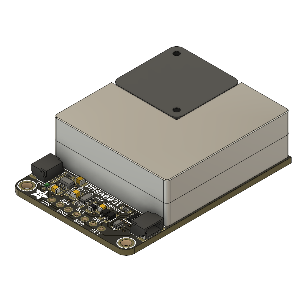
The PMSA003I particulate matter sensor, manufactured by Plantower, plays a crucial role in measuring air quality by detecting and quantifying the concentration of fine particles in the atmosphere. This sensor employs a laser-based scattering technique to measure particle size and provide real-time data on particulate matter levels, particularly focusing on PM1.0, PM2.5, and PM10.
By accurately measuring particle size, the PMSA003I enables the assessment of potential health risks associated with airborne particles - perfect for this project. Fine particles, such as PM2.5, can pose significant health hazards as they can penetrate deep into the respiratory system. Therefore, the sensor's ability to monitor these smaller particles helps in understanding the potential impact on human health in indoor environments.
Additionally, the particulate matter concentration data provided by the PMSA003I is invaluable for evaluating overall air quality. High concentrations of particulate matter can indicate the presence of indoor pollution sources, inadequate ventilation, or the infiltration of outdoor pollutants. By continuously monitoring particulate matter levels, the sensor enables timely detection of air quality issues, facilitating appropriate mitigation measures and interventions to improve indoor environments.
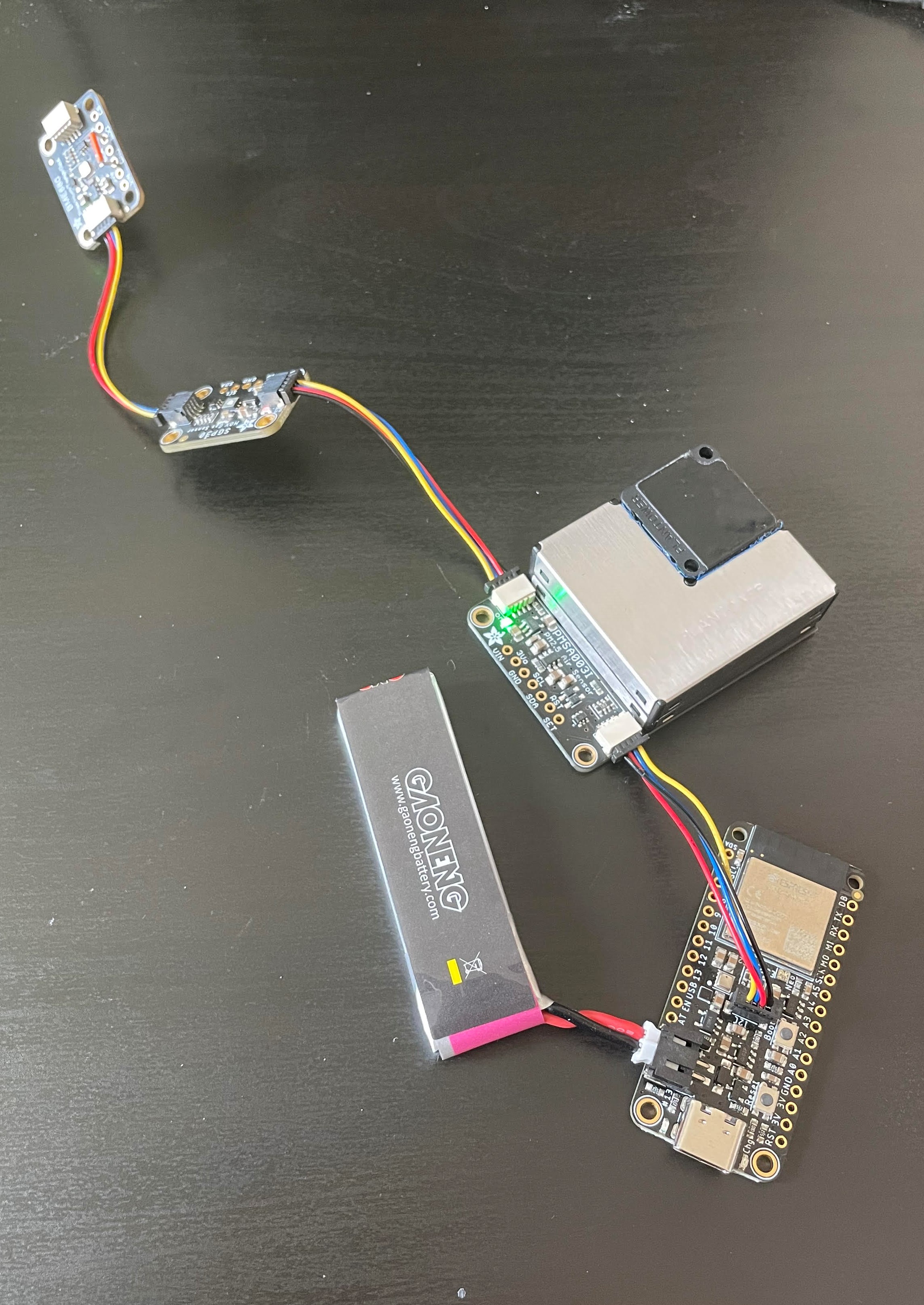
The PMSA003I particulate matter sensor is designed for integration into air quality monitoring systems, enabling easy data acquisition and analysis. This model by Adafruit features I2C via STEMMA QT, allowing seamless connectivity with microcontrollers or other devices. We will be using this connector to integrate all of the sensors in this build
SGP30/40
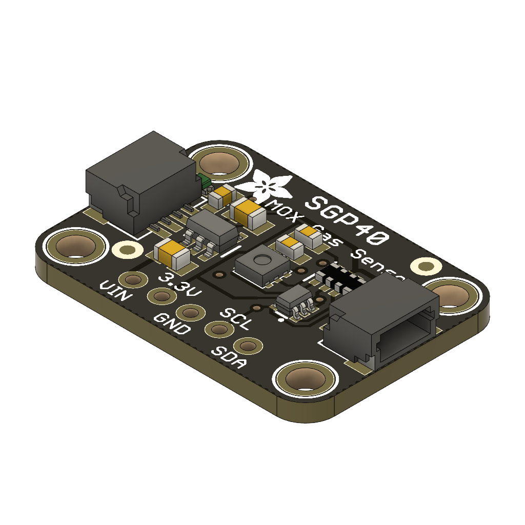
The Adafruit SGP30 is an air quality sensor that plays a crucial role in measuring and assessing indoor air quality. While it does not directly measure CO2 levels, it provides an estimation of equivalent carbon dioxide (eCO2) based on VOC (volatile organic compound) levels.
It is important to note that the Adafruit SGP30 does not directly measure carbon dioxide (CO2) levels. If accurate CO2 measurements are required, specialized sensors designed specifically for CO2 detection could replace this one, but those senors are quite expensive. However, for this application, the estimation of eCO2 provided by the SGP30 is sufficient for assessing general air quality and detecting changes in VOC levels.
In addition to eCO2, the Adafruit SGP30 also measures Total Volatile Organic Compounds (TVOCs). TVOCs encompass a wide range of organic compounds present in the air, including pollutants and odorous substances, which is vital information to determine the quality of the air.
The calibration for this sensor is crucial, as it needs at least 12 hours to acquire baseline measurements of eCO2 and TVOC before it can accurately read data from the environment. In the GitHub repository, I have attached the calibration code I used to obtain the baseline measurements.
BME680
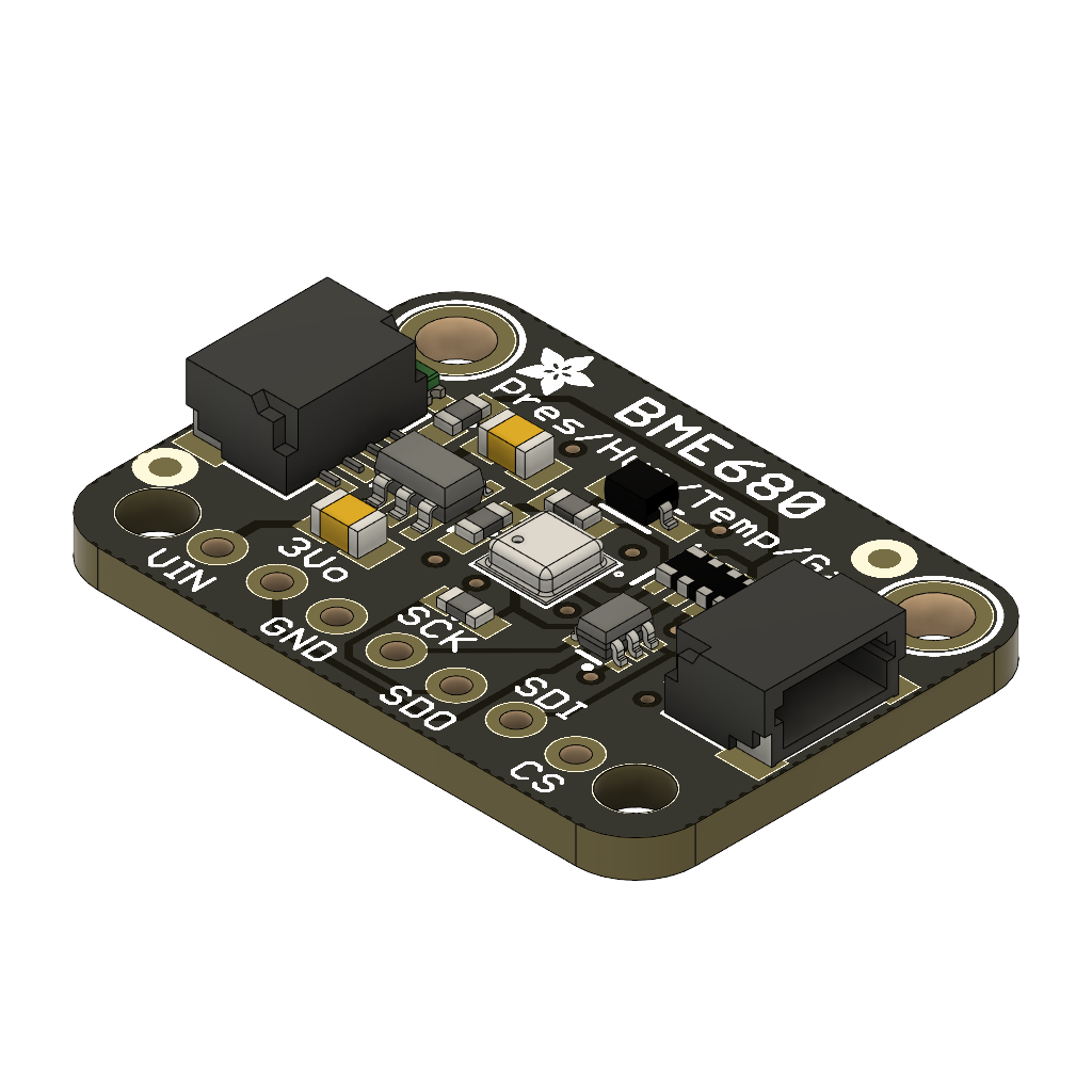
The Adafruit BME680 is a highly valuable sensor for measuring air quality (IAQ) as it provides comprehensive data on multiple environmental parameters, including temperature, humidity, pressure, and volatile organic compounds (VOCs).
One of the key benefits of the BME680 is its ability to measure temperature and humidity accurately. These readings are crucial for understanding the impact of environmental conditions on air quality. Temperature and humidity can affect the behavior of pollutants, chemical reactions, and the overall comfort of indoor spaces. By monitoring these parameters, the BME680 helps identify potential issues such as high humidity levels that may promote mold growth or temperature fluctuations that affect occupant comfort.
In addition to temperature and humidity, the BME680 measures VOCs, which are emitted by various sources and can impact air quality. However, it's important to note that the BME680's VOC readings may not be as precise as those from specialized VOC sensors like the SGP30. Currently the Bosch BSEC2 library is not available in CircuitPython, which is required to calculate IAQ, so the VOC function is not very useful.
To obtain more accurate VOC measurements, the BME680's temperature and humidity readings can be used in combination with the Adafruit SGP30 air quality sensor. By feeding the temperature and humidity data from the BME680 into the SGP30, the VOC readings can be compensated and calibrated for improved accuracy. This allows for a more reliable assessment of air quality, taking into account the influence of environmental conditions.
ESP32-S2
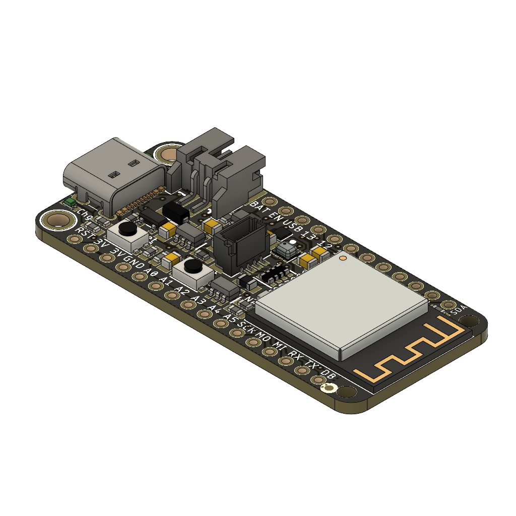
The Adafruit ESP32-S2 Feather is a versatile microcontroller designed for IoT projects. It features a STEMMA QT connector for I2C devices, WiFi capabilities, and flexible battery options. The STEMMA QT connector allows for easy integration of I2C sensors and devices, expanding the microcontroller's capabilities, perfect for connecting the sensors above. The ESP32-S2 Feather supports 2.4 GHz Wi-Fi connectivity, enabling seamless integration with networks and internet services, including MQTT. The microcontroller offers USB Type-C and Lipoly battery support, with built-in charging circuitry and active battery monitoring.
Miscellaneous
I have compiled a list below with other required hardware to create this build. I purchased some of the STEMMA QT connectors from adafruit, some PC-PETG filament from overture, and M2 hardware to assemble the rest of the case and overall build.
If I were to start this project over, and perhaps for the next iteration, I would have used an SCD40 true CO2 sensor as well as a SEN55 to encompass the entire project written in C++. This setup simplifies the amount of sensors dramatically, as well as the cost. Due to stock availability at the time of producing this project as well as not having acces to a soldering iron, I was unable to persue this avenue. I might create an addendum in the future with this hardware arrangement, however.
Bill of Materials (BOM)
| Name | Description | Quantity | Price |
|---|---|---|---|
| ESP32-S2 Feather | ESP32-S2 Feather with STEMMA QT / Qwiic - 8MB Flash No PSRAM | 1 | $18.00 |
| PMSA003I | PM1.0, PM2.5 and PM10.0 concentration in both standard & environmental units | 1 | $45.00 |
| SGP30 | SGP30 Multi-Pixel Gas Sensor, a fully integrated MOX gas sensor | 1 | $18.00 |
| BME680 | temperature, humidity, barometric pressure, and VOC gas sensor | 1 | $19.00 |
| 50mm Long STEMMA Cable | 4-wire cable 50mm long and fitted with JST SH female 4-pin connectors on both ends | 3 | $1.00 |
| PC-PETG Filament | PETG and Polycarbonate mix of 1.75mm 3D Printing filament | 1 | $24.00 |
| Metric M2 Hardware Set | High Quality Stainless Steel 304 Phillips Pan Head Bolts Screws Nuts Flat Washers Kit | 1 | $10.00 |
| $137.00 | |||
Programming
Initial Testing
After obtaining all of the necessary parts, I was able to test the functionality of all the components. I originally wanted to use the Arduino IDE to program in C++ as it was what I was familiar with from my other projects. However, my testing with all of the microcontrollers I had purchased from Adafruit would not upload arduino sketches reliably for testing. I narrowed it down to the serial commands in the setup part of the sketch causing the microcontroller to hang, but after many hours of tinkering I decided to use CircuitPython. While I had worked with traditional Python, CircuitPython was familiar in some aspects, and I was able to get started relatively easily after some research. The only functionality I sacrificed using CircuitPython was the Bosch BSEC2 library for calculating the Indoor Air Quality (IAQ) Index. The source code is not open source, so I was unable to compile a version for CircuitPython, although I tried.
Regardless, I imported all of the necessary libraries and hooked up all of the sensors to the ESP32-S2 via the STEMMA ports. Perhaps in a future project I will attempt creating my own circuit board, but the STEMMA ports provided an easy route for quickly prototyping sensors over I2C. A simple Python script verified all of the sensors were working and I was getting logical readouts on the serial connection. I used the Mu editor to program the controller and debug through the serial port.
From there, I attempted to connect the microcontroller to the internet and connect to an MQTT broker on my home server. I used Mosquitto MQTT via Node-RED to send a JSON file with the sensor data, battery voltage, and other metrics for debugging. I had some initial trouble getting Node-RED to parse the data coming in as a JSON. My biggest hurdle to overcome regarding this was to ensure the variable names in the JSON aligned with the message payload for the Node-RED parser. After that, Node-RED sends the message payload to an influxDB database I set up on the same Raspberry Pi for safe-keeping.
For the final piece of the puzzle, I used grafana installed on a docker container to query the data from the InfluxDB database. I made a dashboard with multiple graphs to track each sensors data with relevant data grouped together for more convenient analysis.
Additional Programming Information
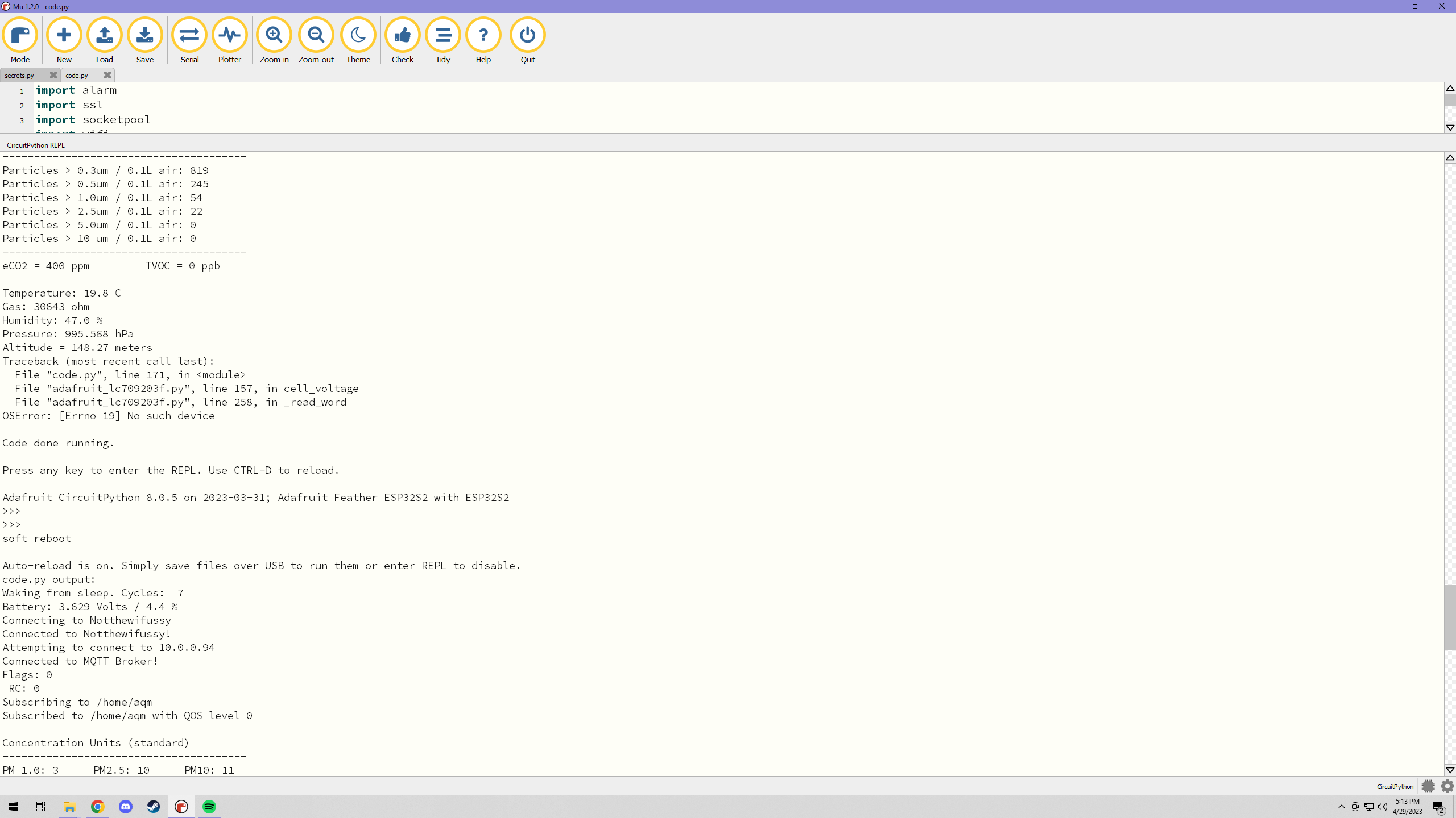
As stated above, I wanted to utilize the Bosh BSEC2 library. I found some information about compiling the BSEC library for CircuitPython, but I was unable to get it working. The versions I could compile no longer existed. As for right now the MOX sensor on the BME680 reads the raw resistance of the sensor. It is still useful for showing the trends as a lower resistance infers more VOCs present and vice versa.
I also tried to lengthen the life of this project and keeping it powered using only a battery with intermittent charging. The PMSA003I only has an 8000 hour duty cycle, or about a year's worth of 24/7 operation. With the amount of time it takes to warm up the sensors for accurate readings (approximately 30-60 seconds) It became really difficult to balance power draw with data collection. Instead of trying to make this project run for as long as possible off of a single 500 mah battery, I decided to run the sensor continuously in order to assess the stability of the system (microcontroller, code, MQTT broker, and InfluxDB database) instead of trying to optimize the sensor's life.
Also, by putting the microcontroller to sleep, the data displayed on Grafana was patchy and inconsistent due to needing to throw away minutes of data on each startup due to the sensors needing ample time to reach steady-state. I wanted clean graphs for my analysis, so I decided for the first iteration of this project to see how far this setup wpuld take me. The next iteration will use the two sensors i mentioned previously for a more optimized long term solution.
Case Design
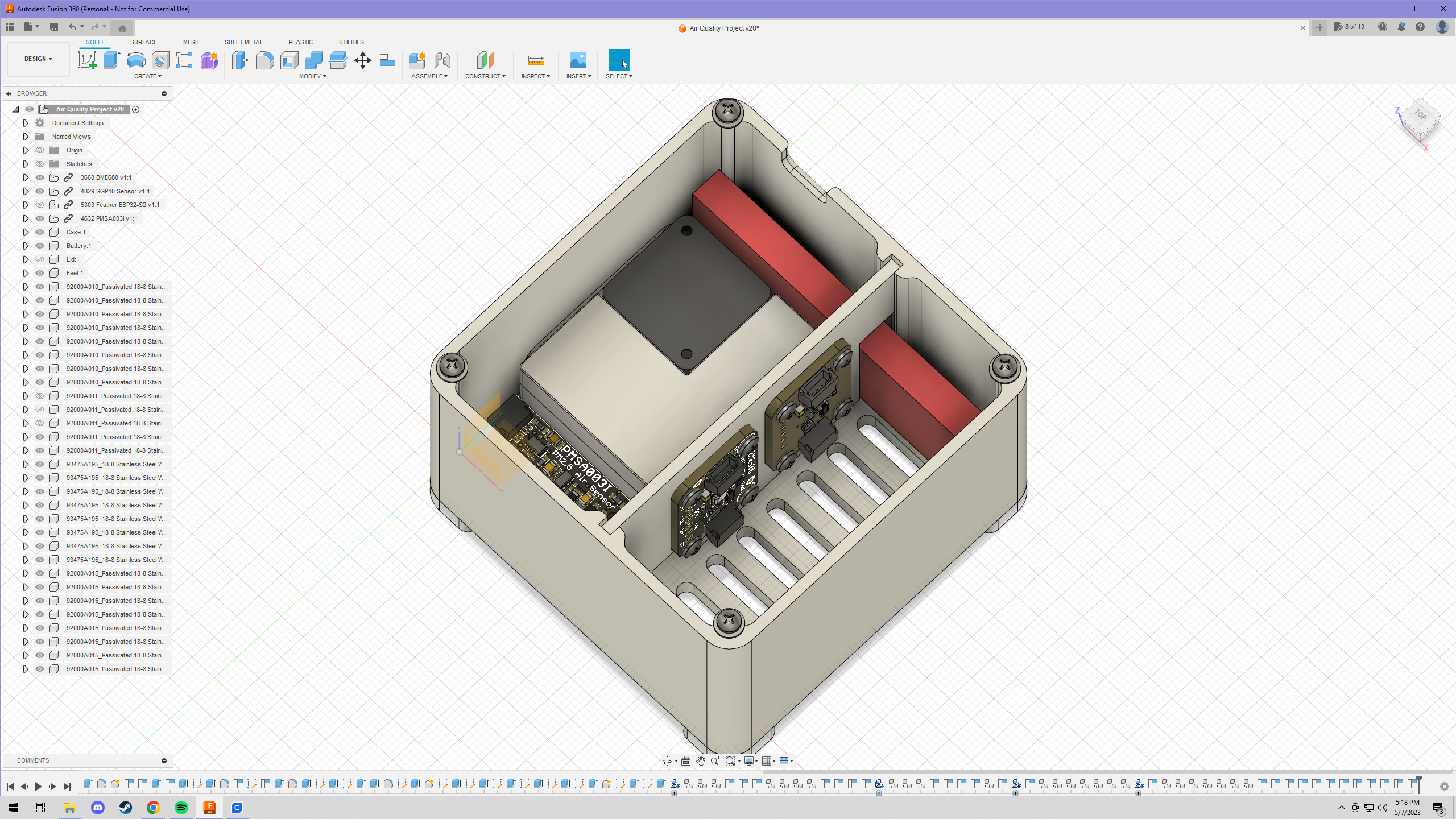
I wanted to keep the case design as minimal as possible. For me, the most practical solution to a problem is through simplicity. I wanted to keep the case as small as possible because it sits on my desk in my workspace. I initially found it a little tricky to lay out all of the parts in CAD with only reference dimensions to go off of. Luckily, Adafruit has STEP files of all of their products, so I was able to manipulate the sesnors in CAD fairly easily. I also took into consideration that all of the sensors need adequate access to the envirnment. I made slots in the side of the case to allow the PMSA003I to draw air in and exhaust it. I also created vent holes through the bottom of the case and lid to allow for passive airflow with the sensors mounted vertically.
Mounting both the BME680 and SGP30 vertically seemed like the most optimal configuration as the product data sheet warmed that dust and particles landing on these sensors could interfere with accurate sensor measurements. I installed a removable slotted wall in the middle of the case bisecting the PMSA003I and ESP32-S2 from the BME680 and SGP30. I wanted to isolate these two components as heat from the ESP32 could result in higher read temperatures from the BME680, and the SGP30 eCO2 and TVOC calculations are base doff the real-time temperature and humidity readings in the code. My forethought payed off, and the readings seem consistent outside of the case and inside.
Grafana
I wanted to keep the case design as minimal as possible. For me, the most practical solution to a problem is through simplicity. I wanted to keep the case as small as possible because it sits on my desk in my workspace. I initially found it a little tricky to lay out all of the parts in CAD with only reference dimensions to go off of. Luckily, Adafruit has STEP files of all of their products, so I was able to manipulate the sesnors in CAD fairly easily. I also took into consideration that all of the sensors need adequate access to the envirnment. I made slots in the side of the case to allow the PMSA003I to draw air in and exhaust it. I also created vent holes through the bottom of the case and lid to allow for passive airflow with the sensors mounted vertically.
Mounting both the BME680 and SGP30 vertically seemed like the most optimal configuration as the product data sheet warmed that dust and particles landing on these sensors could interfere with accurate sensor measurements. I installed a removable slotted wall in the middle of the case bisecting the PMSA003I and ESP32-S2 from the BME680 and SGP30. I wanted to isolate these two components as heat from the ESP32 could result in higher read temperatures from the BME680, and the SGP30 eCO2 and TVOC calculations are base doff the real-time temperature and humidity readings in the code. My forethought payed off, and the readings seem consistent outside of the case and inside.